Advanced Modeling
Recap:
- What is subdivision modeling and how do we use it to make more complex models?
- How to use Edge Loops to change the shape of subdivided models
- Using subdivision to make a die.
- History of the Utah Teapot
- Using subdivision to model the Utah Teapot
Plan:
- The 3D Process Large Scale, Indie and Individual
- Boolean Modeling
- Topology Reduction
- Flow of Topology
- Importing Images
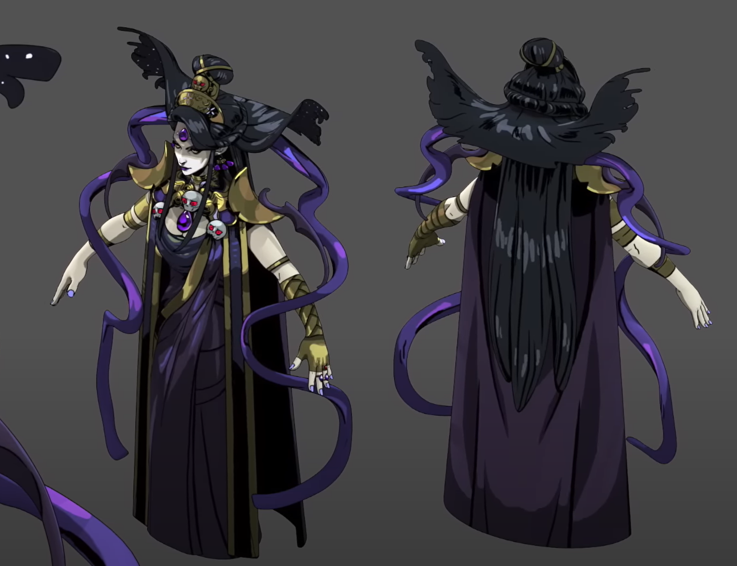
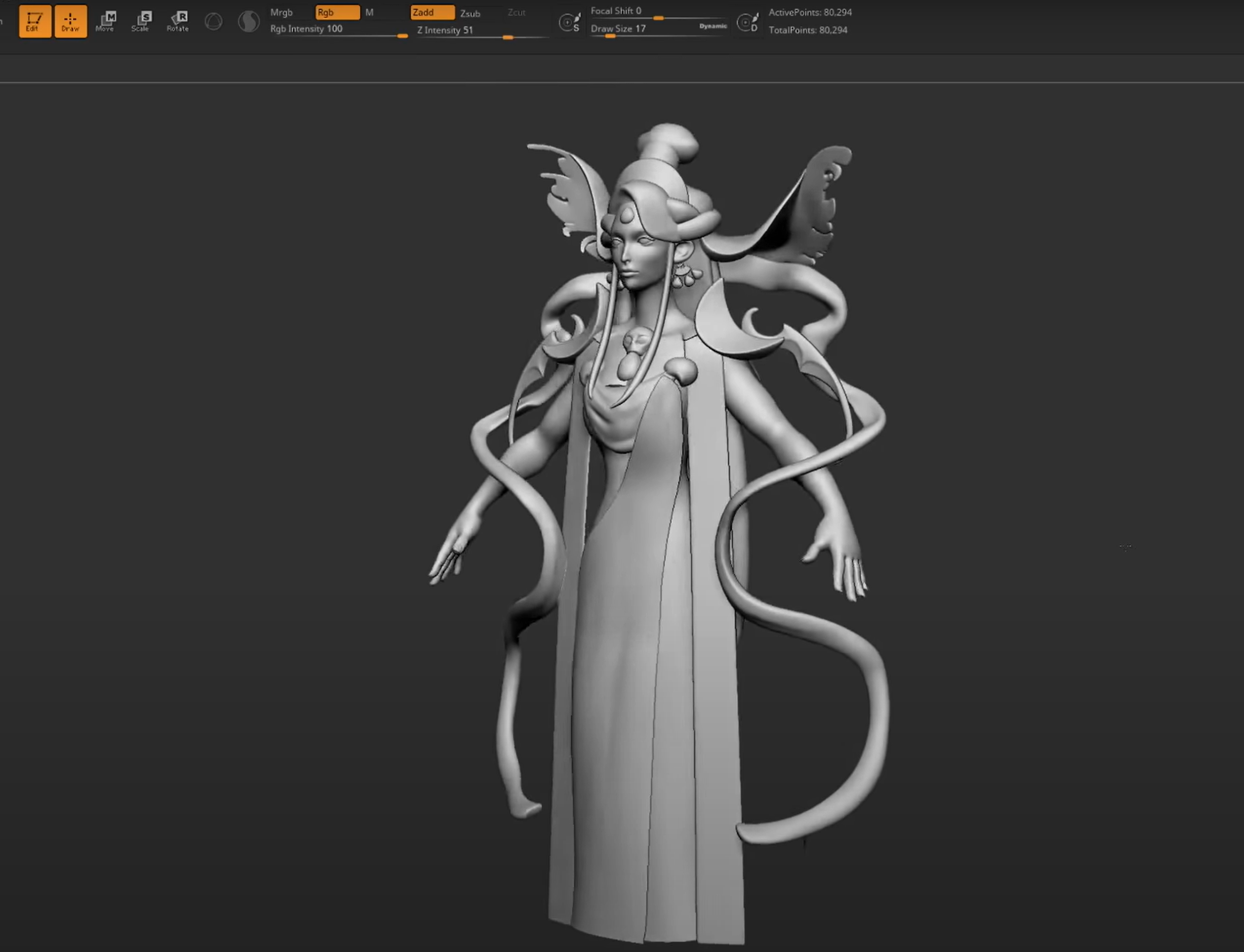
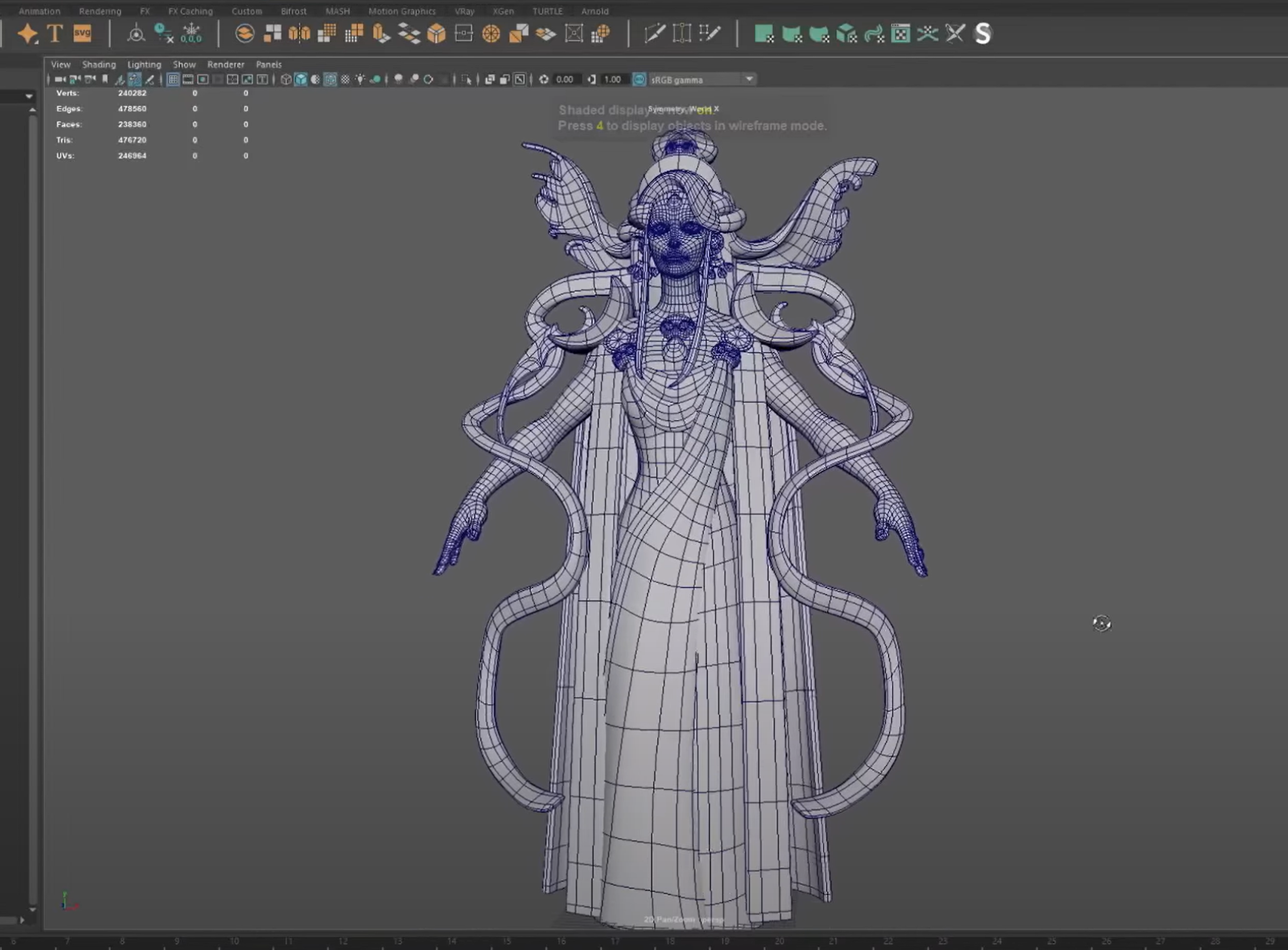
- Modeling complex models from Images
Practice File
Download Practice File
The 3D Process - Disney/Pixar (Luca)
Concept and Story Artist

Modeling Artist
Technical Artist - Rigging
Technical Artist - Surfaces
Camera Artist
Animator
Lighting Artist
Technical Artist - Rendering
- Pro: Larger productions
- Con: Little individual say, long-working conditions
Further Reading/Watching
- The Science Behind Pixar, Museum of Science, Boston
- The Making of Toy Story Documentary
- Into the Unknown: Making Frozen 2
The 3D Process - Super Giant Games (Hades)
Concept Artist
3D Generalist
Sculpting
Modeling - Retopology
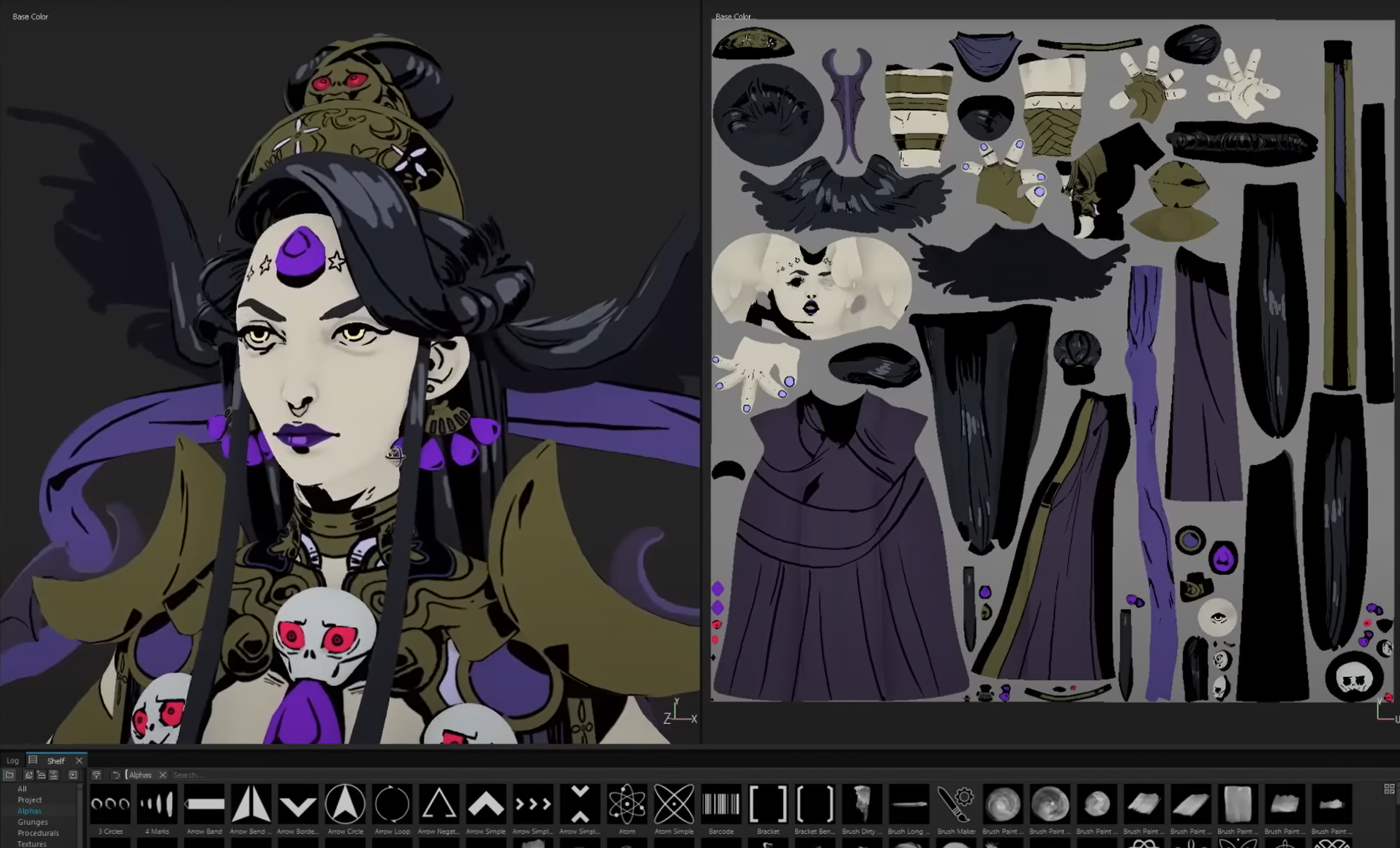
Texturing
Rigging
Animator
Pro: Ability to specialize, exciting projects, individual say Con: Jobs can be unstable, freelance
Further Reading/Watching
The 3D Process - Individual (Real Things, Everywhere)
- Concept
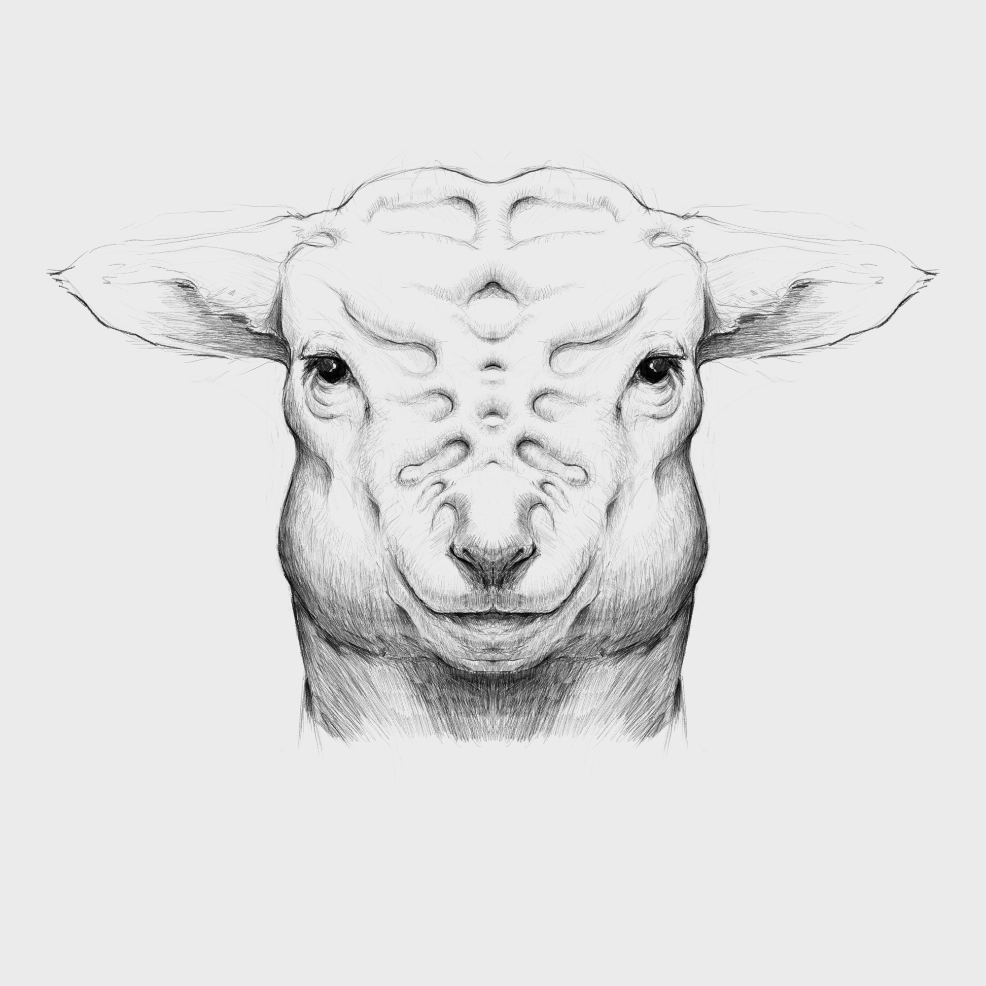
- Initial Sculpting
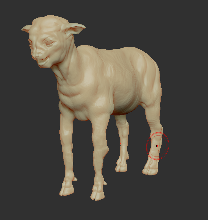
- Refined Sculpting
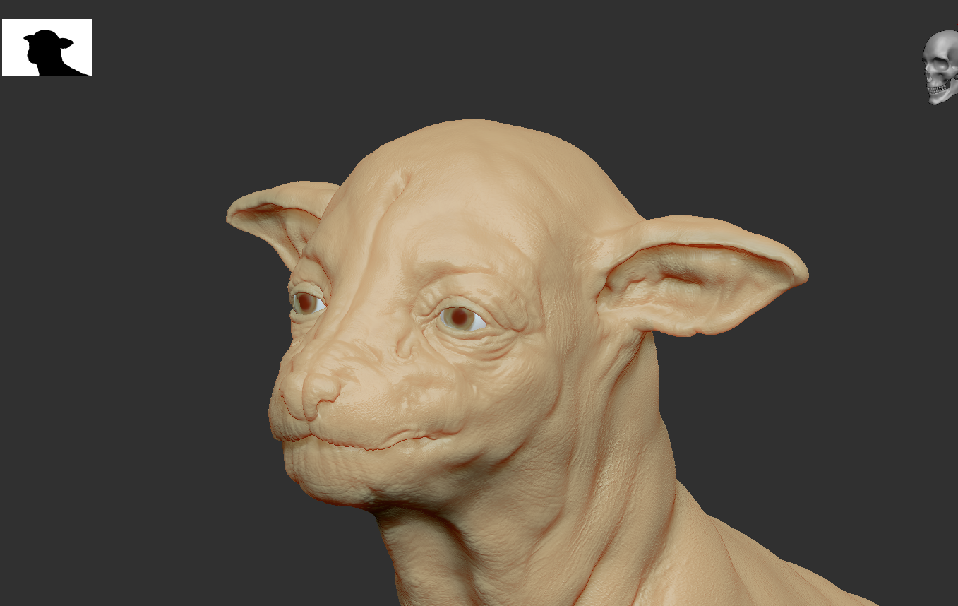
- Retopology (Not Pictured)
- Textures
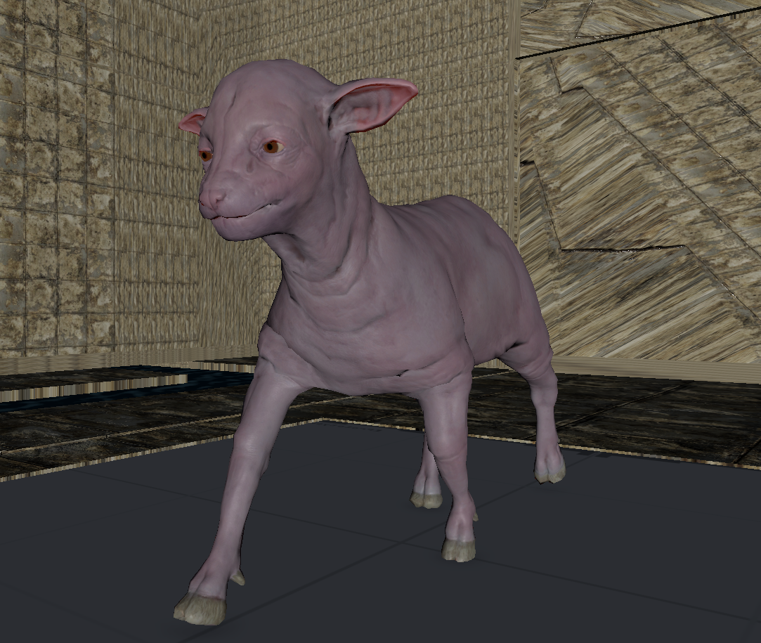
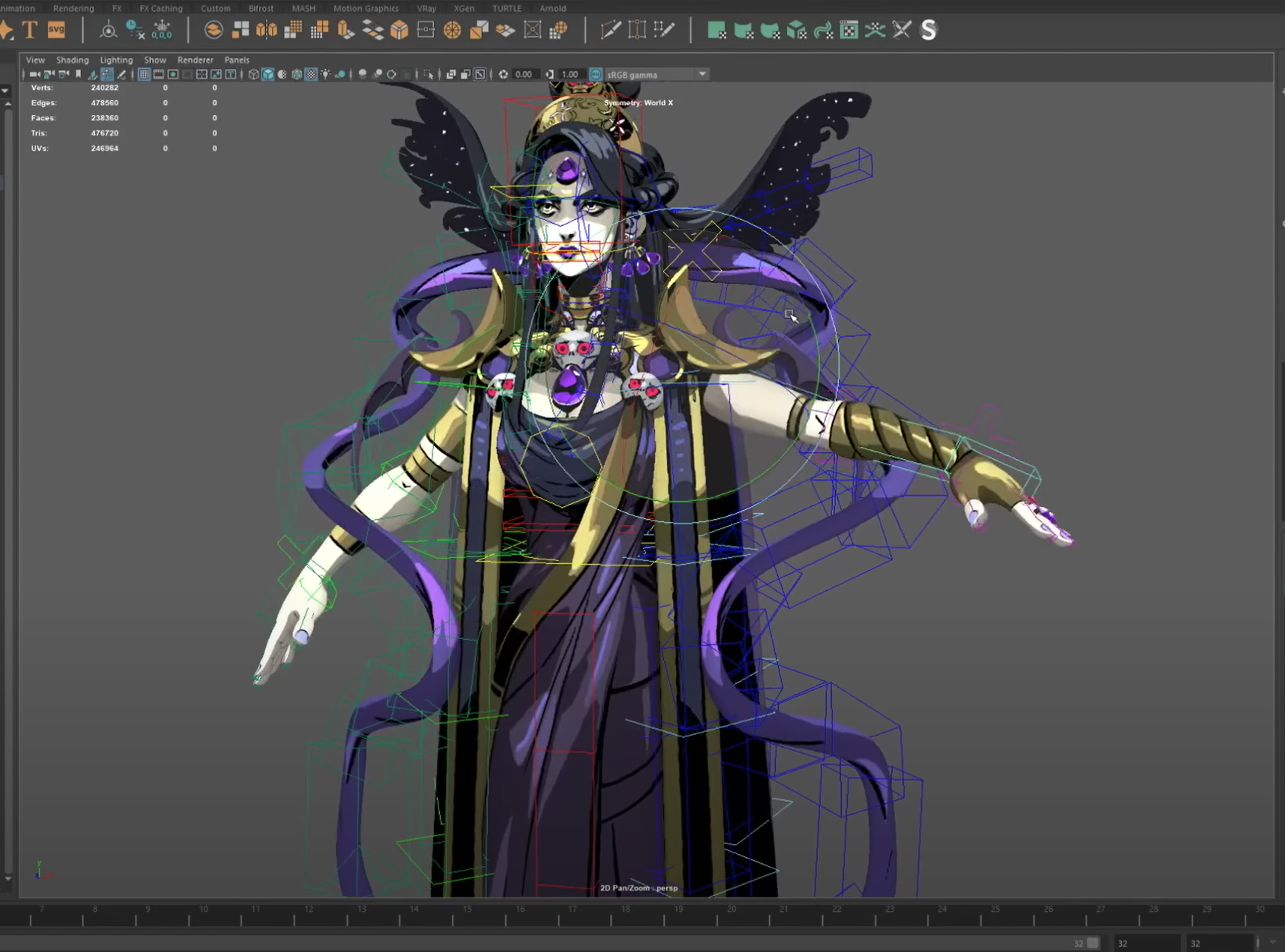
- Rigging
- Animations
- Final Game
Polysphere
Oftentimes, working with the default sphere model within Maya can present many challenges. Since the sphere model does not have even and quadded topology, it can present many issues when creating more complex models.
Most artists when working with spherical shapes use a poly sphere. A polysphere is a sphere made up of quadded geometry that has evenly spaced vertices.
To make a poly sphere:
- Create a sphere primitive
- Create a cube > Smooth 2 Levels > Scale to be size of sphere
- Click on sphere > Press Make Live (Magnet Button)
- Click on Smooth Cube > Mesh > Conform
- Click Make Live > Delete original sphere
Booleans
We can combine meshes together using boolean operations. When using boolean operations, the same rules of quadded topology still apply. We can combine objects together using booleans, however, we must clean up our geometry after the operation is completed.
To make sure your boolean operations can produce clean topology, you should make sure that meshes you are combining together can have their edge loops connected. This often means combining geometry that has the same number of edge loops.
Boolean Subtract
Steps to make cut in using Booleans:
- Place one model inside the other model. Ensure that their edges can be connected after the boolean operation is complete.
- Select the base model > Shift Select the model you want to subtract
- Mesh > Boolean > Difference (A-B)
- To complete the operation navigate to Edit > Delete By Type > History
- Clean up disconnected and loose vertices using the Target Weld tool.
- Clean up nGons using the Multi-cut tool
UI TIP: Press Right-Click after a cut to stop the cutting operation
Steps to combine objects together using Booleans:
- Place one model inside the other model. Ensure that their edges can be connected after the boolean operation is complete.
- Select both models > Mesh > Boolean > Union
- To complete the operation navigate to Edit > Delete By Type > History
- Clean up disconnected and loose vertices using the Target Weld tool.
- Clean up nGons using the Multi-cut tool.
Topology Reduction
When modeling, there are many cases in which we want to reduce the areas of high density topology to low density. Oftentimes, we might have one area of our model that has a lot of detail, while we have other areas that have low detail. We can use topology reduction techniques to go from areas of high poly count to low poly count.
Examples:
3 to 1 Reduction:

5 to 3 to 1 Reduction:
2 to 1 Reduction:
Machine Example:
Topology Flow
When modeling, we often need to adjust the flow of our topology. For example, in the below model, if I want to add in edge loops to give the top part of my object a hard edge, I change the topology of the attached cylinders. After smoothing, this causes the cylinders to have a deformed shape.
Looking at this model, I realize I need to change the flow of my topology to go around the extruded cube. Currently, the topology follows down the sides of the model.
Simplified Example:
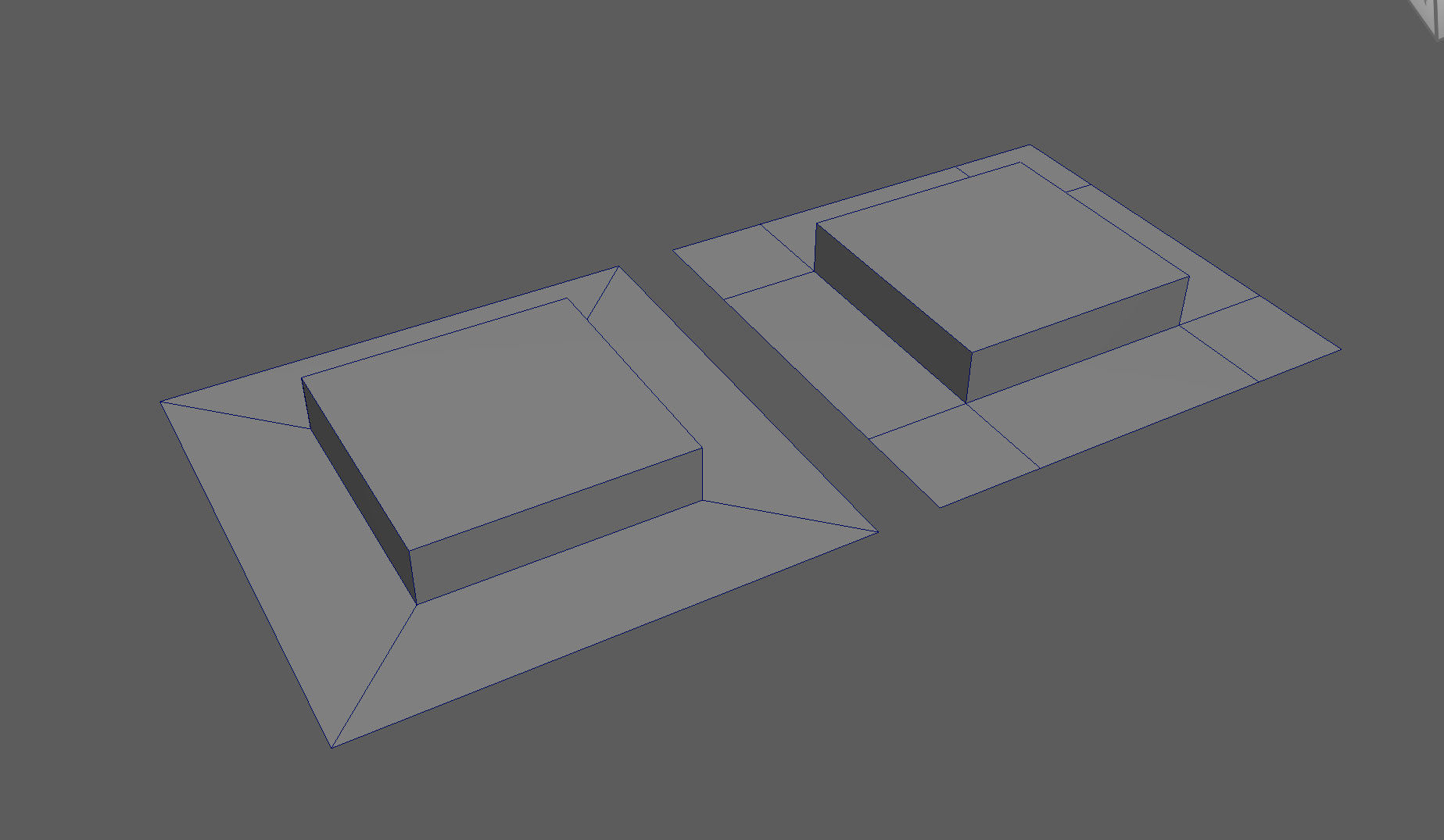
The first object is the topology I want, the second model is the topology I have currently.
Steps to changing the flow of topology in the example:
- Select and Delete the faces where the two sections meet
- Add in extra edge loops to match the edge count for both sections
- Bridge the sections together
- Add the extra edge loops to harden the bottom edges
Free Image Plane
We can use Free Image Planes to bring reference images into our Maya scene. As a note, it is important to store all of your reference images in the Source Images folder within your Maya project.
To bring in an image on a Free Image Plane:
- Create > Free Image Plane
- Select Image Plane > Attribute Editor > Image Plane Shape > File Icon > Choose Image
To lock an Image Plane to a particular view:
-
Move the Image Plane back on the Axis you want to view it in. For example, if I want to view my image through my Front Camera, i’ll move it back on my Z Axis.
-
Select Image Plane > Attribute Editor > Display - looking through camera > Select Camera. Note: You might need to be in that view for the camera to show up on the list. Making Image Planes Reference Objects
It is very easy to accidentally click on reference images. To prevent this, it is best to put your reference images on a separate layer, and make it a reference layer.
Steps:
- Select all of your reference images
- Click the create and add to layer button > Rename Layer
- Set the Layer to Reference